Measuring Relative Intensity Noise (RIN)

What is relative intensity noise?
Relative intensity noise (RIN) is defined as the ratio of mean square photon noise fluctuations, measured within a given bandwidth, to the square of the average optical power. Total measured noise from a laser generally includes shot noise, thermal/system noise, and optical power (total photon energy per second) fluctuations.
Shot noise
Shot noise takes place due to infinitesimal quanta of photon energy arriving randomly at the detector where random current noise is generated at the output of the photodetector.
- How is shot noise measured?
Shot noise can be determined by measuring the average photo current generated by the photodiode where the current is dependent on the average optical power received.
Thermal noise
Thermal/system noise refers to the equivalent noise at the output of the photodetector without optical input where resistive load and amplification are taken into account. It can be measured with an appropriate spectrum analyzer without optical input to the photoreceiver.
Laser noise
Laser noise at the source or excess photon noise is primarily due to the random fluctuation in the intensity of the light generated at the diode, although frequency fluctuation effect exists if dispersive fiber transmission is involved. The term RIN and excess photon noise have been often used interchangeably although it is critical to differentiate the excess photon noise from other sources of noise in applications where excess photon noise is limiting the performance. Excess RIN is informally termed to differentiate between such without contribution from shot noise and thermal noise.
- How is laser intensity noise measured?
The conventional method of measuring total relative intensity noise (RIN) is through photodetection and spectrum analysis. Depending on the level of optical signal received, an additional amplifier may be required to achieve higher equivalent input noise at the spectrum analyzer than the shot noise of the photodetector.
A RIN measurement method includes system/thermal noise and shot noise, and it has been a common practice but not formally standardized. Another method is also available by factoring out thermal/system and shot noise in the analysis, and has been recently referred to as excess RIN.
Careful characterization and setup calibration would be required to accurately measure and analyze excess RIN, particularly for high frequency RIN measurement and analysis. Low noise and high responsivity photodetector along with low noise amplifier are crucial in the measurement setup where a relatively low noise floor sets the sensitivity and capability of the measurement set up.
Ultra-wide bandwidth photodetector and amplifier among other peripheral elements enable high frequency RIN measurement beyond 40 GHz. The resulting noise density spectrum exhibits the laser’s “total” or “excess” RIN level behavior over the specified frequency range in the measurement unit of dB/Hz.
To accommodate the measurement of a very low RIN laser under test (LUT), it is often critical and a great challenge to achieve an ultra-low noise measurement floor. By definition, the excess RIN measurement noise floor is lower than that of the total RIN floor as the shot noise and thermal noise are taken out of the equation in excess RIN measurement analysis.
- Tools for measuring laser relative intensity noise
Automated and configurable RIN analyzers such as the OEwaves HI-Q® OE4001 are readily available on the market to serve various user requirements and applications within a wide range of wavelength bands and frequency ranges.
The OE4001 may be configured for multiple wavelength bands and up to 40 GHz with simple operation on a PC application. The user is able to perform total and excess RIN (optional feature) measurement with the click of a button on the intuitive graphical user interface (GUI), and obtain a clear RIN noise spectrum density plot displayed on the GUI window across the specified frequency range.
Measured shot noise is shown under the advanced window tab and thermal noise may be extracted from the saved data file with the excess RIN measurement option. The quick and accurate RIN measurement reveals the LUT’s RIN characteristics over the entire frequency range assisting the user’s laser development and/or monitoring efforts without struggling and questioning the RIN test setup.
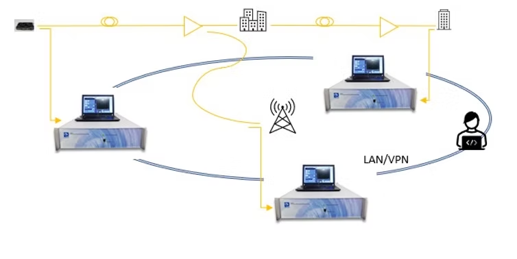
Another useful feature and application with such a RIN analyzer is the capability for remote command via a local area (LAN) or a virtual private network (VPN). The user may send a query and receive data or status via the network remotely by entering manual commands or running his/her own command script per customized LUT testing/monitoring requirements.
To further expand such a usage, multiple analyzers may be deployed throughout a fiber optic network and test/monitor the optical RIN performance at various points along critical links to enable optical network optimization and maximize network performance and reliability.
An example of such an expanded application is shown in the figure below.

%20(1).png)

%20(3).jpg)
%20(1).jpg)
.png)

